About this manual
FEA Studio is a structural analysis and design application. It covers buildings, bridges, towers, roofs and shells, steel connections, foundations and reinforced concrete members. The user manual comes in five parts, one for each stage of the work:
| Part | Covers |
|---|---|
| 1 · Modeling | Starting a project, the workspace, geometry, materials, sections, supports, loads and meshing |
| 2 · Analysis | Studies and the five analysis types, load combinations, the mesh and solvers, running, and reading the results |
| 3 · Design | Code checks and member design for concrete, steel, composite, walls, footings and connections |
| 4 · Drawings | Steel and reinforced concrete shop drawings, drawing standards and export |
| 5 · Reporting | Model, analysis, design and calculation reports; print, PDF, Word and other outputs |
This part describes everything you do before the first analysis.
Conventions
- Menu commands are written as Menu › Group › Command, for example Model › Curves › Line.
- Keys are shown like
Ctrl+SorF5. - Labels in bold are the words you will see on the screen.
- Unless a step says otherwise, the desktop app and the browser version work the same way. Differences are listed in "Desktop and browser" at the end of this part.
Note. FEA Studio stores values in SI units internally. You can enter and read values in the unit system of the project, and you can type a unit with a value (for example 2500 mm) in most number fields.
The workspace
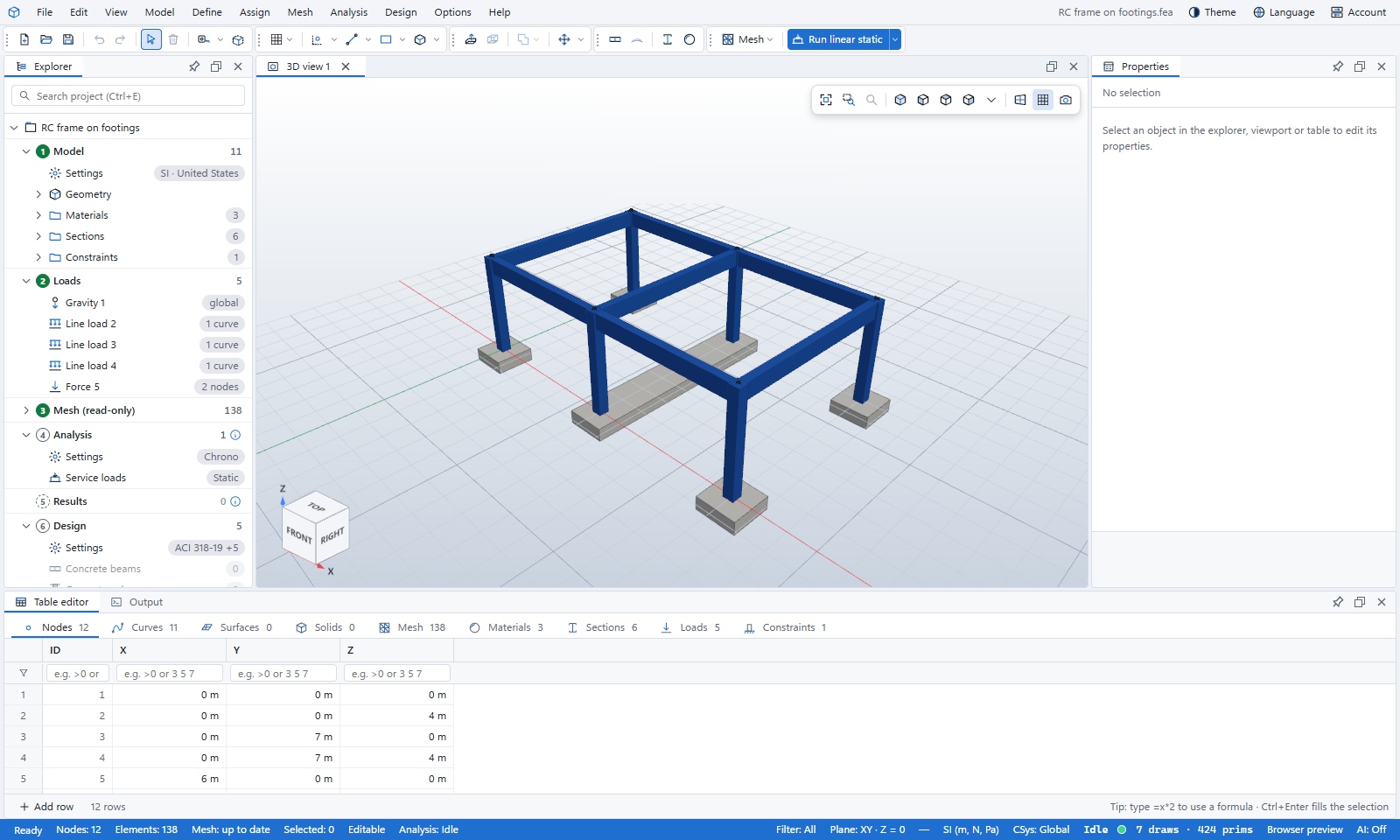
The window has five areas:
| Area | What it is for |
|---|---|
| Menu bar and toolbars | Every command. The toolbars hold the most common ones. |
| Explorer (left) | The project tree, arranged as the numbered stages of the work |
| 3D view (centre) | The model. Several views and document tabs can be open at once. |
| Properties (right) | The settings of whatever is selected |
| Table editor and Output (bottom) | Spreadsheet editing of nodes, curves, materials and loads; the log of every action |
The status bar at the bottom shows the mesh and analysis state, the selection filter, the work plane, the units and the coordinate system. Many of these items can be clicked. For example, clicking Mesh: rebuilds the mesh and clicking Plane: opens the work plane settings.
The Explorer stages
The Explorer arranges the project as numbered stages. Each stage has a status badge, so you can see at a glance what is done and what is still missing.
| Stage | Contains | Typical badges |
|---|---|---|
| 1 Model | Settings, Geometry (nodes, curves, surfaces, solids, groups), Materials, Sections, Constraints | empty · no supports · 11 objects · imported |
| 2 Loads | Load cases and their loads | 2 cases · 5 loads · none |
| 3 Mesh (read-only) | Mesh settings, elements by type, mesh nodes, quality | not built · out of date · up to date |
| 4 Analysis | Settings (the solver of each study), Studies | no studies · 1 study · not run · run |
| 5 Results | Result sets | after analysis |
| 6 Design | Settings (design settings, load combinations), Beam lines, column stacks, slabs, footings, connections… | items with ✓ or ✗ and a utilisation |
| 7 Drawings | The drawing set | none yet · 12 drawings |
| 8 Reports | Model, analysis and design reports | 3 of 3 ready |
Design, Drawings and Reports appear only when they have content, and the stages are renumbered when some are hidden. The Settings item of a stage opens the dialogs that set it up: Model › Settings opens Project settings (name, description, unit system), Analysis › Settings the solver of each study (Part 2), and Design › Settings the design settings and load combinations (Part 3).
- Use the search box at the top (
Ctrl+EorCtrl+F) to find any item by name. - Press
F2to rename the selected item. - Right-click any folder or item for the commands that apply to it. For example, the Materials folder offers Add material and Open in table, and the Sections folder offers Add profile and Add from section library….
Menus
The menu bar of FEA Studio has these menus: File, Edit, View, Model, Define, Assign, Mesh, Analysis, Results, Design, Drawings, Options and Help. At the right of the title bar are Theme, Language and Account.
- Model draws the geometry.
- Define sets up what the model is made of and loaded by: Materials…, Steel sections…, Section designer, Load cases and Load combinations.
- Assign gives the selected objects a material, section or shell, loads and supports, and runs the load generators.
Menus open as wide panels with commands grouped under headings. Each panel has a search box, and its shortcut keys are shown beside the commands.
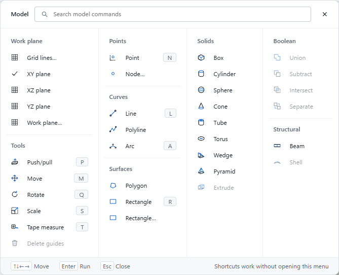
- Simplified menus (Options › Workspace) is on by default. It shows only the menus the current stage needs:
- While the model can be edited, you see Model, Define, Assign and Mesh.
- Once the model has results, these are replaced by Results and Drawings.
- Menu style (Options › Workspace) switches between the modern panels and classic drop-down menus.
- Press
AltorF10to reach the menus from the keyboard.
Toolbars
The toolbars run below the menu bar. Press Ctrl+F1 to show or hide them.
| Toolbar | Commands |
|---|---|
| Standard | New, Open, Save · Undo, Redo · Select, Delete · Measure ▾ · Clipping box |
| Draw | Work plane ▾ · Points ▾ · Curves ▾ · Surfaces ▾ · Solids ▾ |
| Modify | Push/pull, Extrude · Boolean ▾ · Transform ▾ (Move, Rotate, Scale) |
| Properties | Beam, Shell · Steel sections, Materials |
| Analysis | Mesh ▾ (Show mesh, Check quality) · Run linear static ▾ (the drop-down picks another analysis type) |
| Results | Shown after an analysis: result set, quantity, case, Display, scale, Design…, D/C ratios, Unlock model |
Panels and layouts
You can drag panels to dock them anywhere, stack them as tabs, pin them or float them.
- Options › Panels shows or hides each panel: Explorer, Properties, Table editor, Output, Mesh quality, Connection and Template panel.
- Options › Workspace › Layouts switches between ready-made arrangements (Modeling, Analysis, Viewport focus). Use Save current layout as… to keep your own arrangement and Reset layout to go back to the default.
- Panels follow the stage. While you model, the Results panel is hidden. Once the model has results, the Table editor, Mesh quality and Template panels are hidden. They come back in their old place when you return to that stage.
Starting a project
The Start dialog
When FEA Studio opens with nothing loaded, it shows Welcome to FEA Studio. File › New… (Ctrl+N) and File › Samples open it again at the matching page.
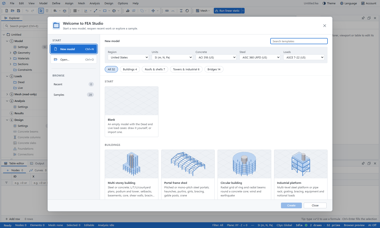
| Option | What it does |
|---|---|
New model (Ctrl+N) | Opens the template gallery with the units and design-code bar |
Open… (Ctrl+O) | Opens a .fea project or an importable model file |
| Recent | Files you opened before (desktop app) |
| Samples | 28 ready-made example models grouped by type |
Samples open as new, unsaved models, so the original files are never changed. Use the chips (Simple, Complex, Concrete beams, Concrete slabs, Composite design, Shear walls, Foundations, Steel connections, IFC models) or the search box to find one.
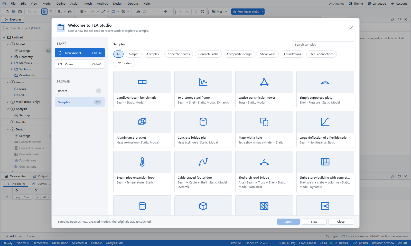
New model: region, units and design codes
File › New… (Ctrl+N) opens the New model page. Pick the units and design codes first, then choose a blank model or a template.
| Field | Choices |
|---|---|
| Region | United States, Korea, Europe, Canada, Australia, India, China, Philippines, Custom |
| Units | SI (m, N, Pa) · SI (mm, N, MPa) · US (in, lbf, psi) |
| Concrete | ACI 318 · KDS 14 20 · Eurocode 2 · CSA A23.3 · AS 3600 · IS 456 · GB 50010 · NSCP 2015 |
| Steel | AISC 360 LRFD · AISC 360 ASD · KDS 14 31 · Eurocode 3 · CSA S16 · AS 4100 · IS 800 · NSCP 2015 |
| Loads | ASCE 7-22 · KDS 41 · Eurocode |
Choosing a Region fills in all the other fields:
| Region | Units | Concrete | Steel | Loads |
|---|---|---|---|---|
| United States | US (in, lbf, psi) | ACI 318 | AISC 360 LRFD | ASCE 7-22 |
| Korea | SI (mm, N, MPa) | KDS 14 20 | KDS 14 31 | KDS 41 |
| Europe | SI (m, N, Pa) | Eurocode 2 | Eurocode 3 | Eurocode |
| Canada | SI (mm, N, MPa) | CSA A23.3 | CSA S16 | ASCE 7-22 |
| Australia | SI (mm, N, MPa) | AS 3600 | AS 4100 | ASCE 7-22 |
| India | SI (mm, N, MPa) | IS 456 | IS 800 | ASCE 7-22 |
| China | SI (mm, N, MPa) | GB 50010 | Eurocode 3 | Eurocode |
| Philippines | SI (mm, N, MPa) | NSCP 2015 | NSCP 2015 | ASCE 7-22 |
The region also sets the default drawing standard and sheet size; see Part 4. If you change one code by hand, the region becomes Custom, unless the new set of codes matches another region exactly.
Tip. Pick the region before you choose a template. The codes you set here carry through to load combinations, member design, footings, connections and drawings, so you will not have to set them again in each module.
Templates
Below the setup bar is the template gallery. A template builds a complete parametric model: members, supports, load cases and studies. It then meshes the model and runs its load generators, with a progress card while it works.
The first card, Blank, gives an empty model with the load cases Dead (self-weight on) and Live. Use it to draw a model yourself or to import one.
| Family | Templates |
|---|---|
| Buildings (4) | Multi-storey building · Portal frame shed · Circular building · Industrial platform |
| Roofs & shells (7) | Double-layer grid · Arch roof truss · Barrel vault · Dome · Hemispherical shell with a hole · Hyperbolic paraboloid · Cooling tower |
| Towers & industrial (6) | Lattice tower · Transmission tower · Chimney / stack · Storage tank / silo · Pipe rack · Stair |
| Bridges (14) | Bridge superstructure · Single-span overpass · Multi-span overpass · Waterway crossing · Straight flyover · S-curve flyover · U-turn flyover · 270° ramp · Truss bridge · Plate girder bridge · Box girder bridge · Tied arch bridge · Cable-stayed bridge · Suspension footbridge |
To create a model:
- Choose a family chip, or type in Search templates.
- Click a card, then click Create. You can also double-click the card, or select it and press
Enter. - The model is built, meshed and loaded. It opens ready for analysis.
Changing template parameters later
Options › Panels › Template panel shows the template's parameters, grouped as in the template form. Every change regenerates the model as one undo step.
- If you have edited the model by hand, FEA Studio asks Regenerate the model? first.
- The panel is blocked while the model has results; unlock the model first (see "Locked models").
Bridge components
In a bridge template you can change components one at a time. Click a girder, diaphragm, bearing, pier or abutment in the 3D view, then choose in Changes apply to how far the change should reach. For example:
- This girder (G1, span 2)
- G1 in every span
- Every girder of span N
- Every exterior girder
- Every girder
| Component | What you can change |
|---|---|
| Girder | Section (for example AASHTO BT-63), end blocks, plate dimensions |
| Diaphragm | Present, Thickness, Depth |
| Bearing | Type (From the layout, Pot fixed, Pot guided (free along / across), Pot free, Elastomeric), plan size, height |
| Pier | Single column, Multiple column, Wall column, Multiple pile, Box girder (flared column); foundation type (isolated or combined footing, pier pile, pile shaft, pile group) |
| Abutment | This abutment or both |
Use Select them to see every component a change affects, Copy the changes of this … to … to repeat a change elsewhere, and Reset to template or Reset all to undo your changes.
Opening, importing and saving
| Command | What it does |
|---|---|
File › Open (Ctrl+O) | Opens a .fea project |
| File › Recent | Recently used files (desktop app) |
| File › Samples | The sample models |
File › Save (Ctrl+S) / Save as… (Ctrl+Shift+S) | Writes the .fea project file. In the browser the file is downloaded. |
| File › Import | Abaqus input (.inp), Abaqus/CAE (.cae), Abaqus output database mesh (.odb), Nastran bulk data (.bdf, .dat, .nas), MIDAS Civil / Gen (.mct, .mgt, .mcb, .mgb, .mgbx), ETABS text model (.e2k, .$et), nodes from CSV |
| File › Import IFC | Builds a structural model from an IFC building model (Revit, ArchiCAD, Tekla and others); .ifczip is accepted |
| File › Import Revit model | Reads a Revit .rvt file directly and builds the structural model from it |
| File › Update from newer IFC · Load IFC model | Brings changes from a newer IFC of the same building; shows an IFC model in the background |
| File › Export | Abaqus .inp, MIDAS .mct, Nastran .bdf, VTK, nodes and elements as CSV, IFC (structural analysis model, physical model, or with results), a PNG image of the 3D view; Export connections to IFC… writes the steel connections |
You can also drop a file anywhere on the window to open it.
If you close FEA Studio with unsaved changes, it asks whether to Save, Don't save or Cancel. After a crash, it offers to Recover the last state.
Import IFC
Import IFC opens a dialog that lists the element types found in the file. Tick the roles you want: columns, beams, braces, slabs, walls, footings, bearings and other elements. The other settings are:
| Setting | Default | Meaning |
|---|---|---|
| Joining tolerance | 300 mm | Ends closer than this are joined |
| Drop faces narrower than | 150 mm | Removes slivers |
| Joints | Rigid links (members stay on their axes) | Or Move ends onto the axes (centre lines) |
| Supports at the base | Fixed | Or Pinned |
| Walls | Load-bearing (or concrete / masonry) | Or All walls, or None |
| Slabs on grade | Off | Include ground slabs |
| Sloped slabs | Flat plate, average depth | Or thinnest part, thickness below, or leave out |
| Area loads | Superimposed dead 1.5 kPa · Live (floors) 3 kPa · Live (roofs) 1 kPa | Added as load cases |
| After import | Make design objects · Show the BIM model | Beam lines, stacks and so on; the IFC shown in the background |
If the IFC file also contains a structural analysis model, FEA Studio asks whether to use the Building elements or the Analysis model.
Project information
Click the project name at the top of the Explorer to see the project sheet in Properties, or double-click Model › Settings in the Explorer for the Project settings dialog.
- Name and Description appear on every report cover and page header.
- Unit system sets the units used for input and in reports. Values are always stored in SI.
You can also change the units from the units item in the status bar.
Drawing the geometry
The geometry is made of nodes, curves (lines, polylines and arcs), surfaces and solids. Curves become beams, trusses or cables; surfaces become shells; solids become solid elements. You give each one a section or material in a later step (see "Materials and sections").
Structural grid
A grid of named axes and levels makes drawing quick, because the drawing tools snap to every grid crossing at every level.
Model › Work plane › Grid lines…
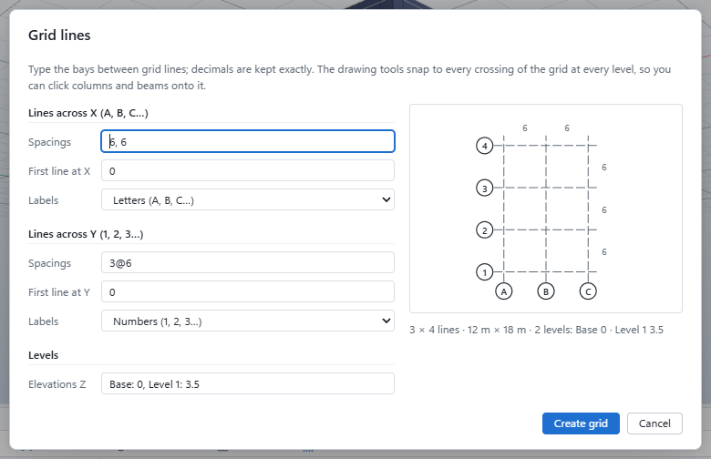
| Field | Example | Notes |
|---|---|---|
| Lines across X (A, B, C…) · Spacings | 6, 6 or 5@6.125 | Bay widths; repeats, units (6125 mm) and formulas (=36.7/2) are allowed |
| First line at X | 0 | Where the first axis lies |
| Labels | Letters (A, B, C…) or Numbers (1, 2, 3…) | |
| Lines across Y (1, 2, 3…) · Spacings | 3@6 | |
| Levels · Elevations Z | Base: 0, Level 1: 3.5 | Name: elevation, separated by commas |
Click Create grid. Later, the same command opens Edit grid lines, where you can use Update grid or Remove grid. Options › Display › Grid lines shows or hides the grid bubbles and level tags.
Work plane
The drawing tools draw on the work plane unless they snap to existing geometry.
- XY plane draws on a horizontal plane (plans, floors). It passes through the selected node, or else lies at Z = 0.
- XZ plane and YZ plane are vertical planes for elevations.
- Work plane… sets the plane and its position (At) exactly, and can turn the view to look straight at it.
The current plane is shown in the status bar, for example Plane: XY · Z = 0.
Points and curves
| Tool | Key | How to use it |
|---|---|---|
| Point | N | Click to place nodes. They snap to endpoints, edges, faces and the grid. |
| Node… | – | Type X, Y, Z in a dialog |
| Line | L | Click the start, then the end, or type a length. Clicks chain lines together; Enter ends the chain. With two nodes selected, the line is made at once. |
| Polyline | – | Click points; Enter or a double-click finishes |
| Arc | A | Start point, a point on the arc, end point; or select 3 nodes first |
Surfaces
| Tool | Key | How to use it |
|---|---|---|
| Polygon | – | Click the corners, then close it by clicking the first point, pressing Enter or double-clicking |
| Rectangle | R | First corner, then the opposite corner, or type length, width. It lies on the face you start on, or else on the work plane. |
| Rectangle… | – | Dialog with Corner X/Y/Z, Width (X) and Depth (Y) |
Typing exact values
While a tool is active, start typing to open the Measurements box at the cursor. Press Enter to apply the value.
| You type | Meaning |
|---|---|
4 or 2500 mm | A length along the current direction |
3, 2 | Absolute x, y on the work plane (or a rectangle's length, width) |
@1.5, 2 | Relative offset dx, dy |
@4<30 | Relative length 4 at 30° |
3*cos(rad(30)) | A formula |
Inference snapping
As you move the cursor, FEA Studio shows what it snaps to: Endpoint, Midpoint, On Edge, On Face, Intersection, Grid Intersection, Guide Point, On Guide, On Red/Green/Blue Axis, From Point and Parallel to Edge.
- Press
→to lock the red X axis,←for the green Y axis and↑for the blue Z axis. Press↓to release the lock. - Hold
Shiftto keep the current snap while you move. Backspaceremoves the last point,Enterfinishes andEsccancels.- While a tool is active, the right-click menu offers Finish, Undo last point, Cancel and the axis locks.
Solids
Model › Solids adds primitive solids through a dialog. Each dialog takes an origin (X, Y, Z), an axis (X, Y or Z) where it applies, the dimensions and a material. You can change the dimensions and rotation later in Properties.
| Primitive | Origin | Dimensions (defaults) |
|---|---|---|
| Box | Corner | Size X, Y, Z (1) |
| Cylinder | Base centre | Radius 0.5, Height 2 |
| Sphere | Centre | Radius 0.5 |
| Cone | Base centre | Base radius 0.5, Top radius 0 (more than 0 gives a frustum), Height 1 |
| Tube | Base centre | Outer radius 0.5, Inner radius 0.4, Height 2 |
| Torus | Centre | Ring radius 1, Tube radius 0.25 |
| Wedge | Corner | Length X 2, Width Y 1, Height Z 1 |
| Pyramid | Base centre | Base width 1, Base depth 1, Height 1 |
Extrude turns selected surfaces into solids along a vector you type.
Boolean operations
Select two or more solids, then choose a command from Model › Boolean:
- Union joins them.
- Subtract cuts the other solids away from the first one you selected.
- Intersect keeps the common part.
- Separate undoes a boolean.
The original solids stay editable as parts of the result.
Push/Pull, Move, Rotate and Scale
| Tool | Key | How to use it |
|---|---|---|
| Push/pull | P | Click a surface or solid face, move the mouse and click, or type a distance. Clicking a line sweeps it into a surface, and ↑ pulls it straight up. A double-click repeats the last distance. |
| Move | M | Base point, then the destination, or type a distance |
| Rotate | Q | Centre (a protractor lies on the face under the cursor; the arrow keys pick the axis), then the start and end of the angle, or type an angle |
| Scale | S | Fixed point, reference point, then a factor |
| Tape measure | T | Measures between two points and leaves guide lines or guide points. Click on an edge to make a parallel guide. Delete guides removes them all. |
Tip. To make copies with Move or Rotate, tap Ctrl to switch copy mode on. Right after the first copy, type x5 to make 5 copies at the same spacing, or /5 to spread 5 copies over the distance.
The same transforms are available as dialogs from Edit › Transform:
- Move… takes ΔX, ΔY, ΔZ.
- Rotate… takes the axis, angle and centre.
- Duplicate… (
Ctrl+D) takes an offset and the number of copies. It also has a Copy supports and loads option and shows a live preview.
Edit › Flip mirrors the selection about its centre along X, Y or Z.
Groups, clipboard and undo
- Make group (
Ctrl+G) groups curves, surfaces and solids. Clicking one part selects the whole group;Alt+clickselects a single part. Ungroup isCtrl+Shift+G. - Cut, Copy, Paste work as usual. Pasted nodes that land on existing nodes are merged with them.
- Undo is
Ctrl+Zand Redo isCtrl+Y. Every edit can be undone, including template regeneration.
The Table editor
The Table editor at the bottom lists Nodes, Curves, Surfaces, Solids, Mesh, Materials, Loads and Constraints in tabs.
- You can edit cells directly and filter columns (for example
>0). - Type a formula such as
=x*2in a cell. Ctrl+Enterfills the selected cells with the same value.
Materials and sections
The Define menu
The Define menu sets up what the model is made of and how it is loaded: materials, sections, load cases and load combinations.
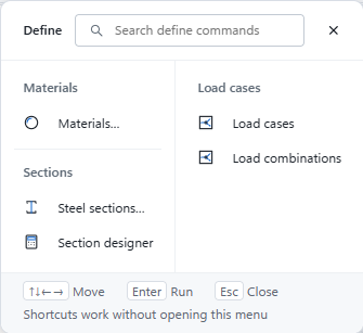
Materials
Define › Materials… opens the Materials dialog. It lists the project's materials on the left; select one to edit it on the right, and click Apply to keep your changes.
- Add material creates a new material. Choose its Type: Concrete, Steel, Rebar or Other. The type decides which strengths it has: f′c for concrete, fy and fu for steel and rebar.
- Add from the library picks materials from the built-in libraries, and from your own library of materials you saved before. Tick the sources and the materials you want. The built-in libraries include:
- Structural steel (EN 10025): S235, S275, S355, S460
- Steel (ASTM): A36, A572 Gr. 50, A992, Stainless 304, Stainless 316
- Concrete (EN 1992): C20/25 to C50/60
- Aluminium and others: Al 6061-T6, Al 6082-T6, Ti-6Al-4V, Timber C24, Glulam GL24h
- Every material has Elastic properties (Young's modulus E, Poisson's ratio ν) and Physical properties (density ρ, thermal expansion α).
The concrete and steel design modules (Part 3) take f′c and fy from the material of each member. You can also select a material in the Explorer's Materials folder and edit it in Properties.
Sections (profiles)
Define › Steel sections… opens the Section library.
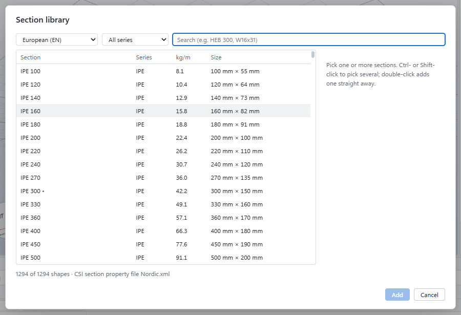
- Pick a catalog: AISC (US), CISC (Canada), European (EN), UK, KS (Korea), AS/NZS or IS (India).
- Narrow the list with the series filter, or type a name such as
HEB 300orW16x31. - Select one or more sections (
Ctrl+clickorShift+click) and click Add. A double-click adds one section at once.
To make your own section, right-click the Sections folder and choose Add profile. The shapes are Rectangle, Circle, Pipe, Box, I-Section, Channel, Tee, Angle and General. Enter the dimensions in the profile's Properties afterwards. Properties also shows the computed Area, Iy, Iz, J, the extreme fibres and the principal axes.
Define › Section designer opens the section designer as a tab of the main area: draw a section of any shape, read its properties, and click Use in model to add it to the model's sections. The designed sections are saved in the project.
Assigning sections to curves
- Select the curves.
- Choose Assign › Properties › Section… (or Model › Structural › Beam, or right-click › Assign section…).
- Choose the Element type (Beam, Truss or Cable), the Material and the Profile.
With no curves selected, Beam adds a new beam between two nodes that you choose in the dialog. Section… also offers New pipe for a tube of any size (a monopile or a tower leg). Assign › Properties › Material… changes only the material of the selected curves, shell surfaces and solids.
The curve's Properties then control how the section sits:
- Section rotation (°) turns the section about the member axis. At 0°, local z points to global Z (for vertical members, to global X).
- Section position places the section relative to the curve: Default, Centroid, Top of section, Bottom of section or Custom. With Default, level beams hang below the curve with their top flush, while columns and braces stay centred.
- Offset y / Offset z move the section away from the nodes. It stays rigidly tied to them.
Assigning shells to surfaces
- Select the surfaces.
- Choose Assign › Properties › Shell (or Model › Structural › Shell, or right-click › Assign shell…).
- Enter the Thickness and the Material.
In the surface's Properties, Section position (Default, Mid-surface, Top face, Bottom face or Custom) and Offset set where the shell sits.
Note. Turn on Options › Display › Realistic to see members and shells drawn with their true sections and thicknesses. Curve lines adds the centre lines on top.
Supports
Select nodes, curves, surfaces or solid faces, then choose a command from Assign › Constraints:
| Command | Restrains |
|---|---|
| Fixed | All six degrees of freedom |
| Pin | The three translations; rotations stay free |
| Roller | The vertical translation (Uz) only |
| Symmetry | A symmetry plane; choose the plane normal X, Y or Z |
| Custom | Each of Ux, Uy, Uz, Rx, Ry, Rz set to Restrained or Free |
A support on a curve, surface or face applies to every mesh node on it. The Explorer's Model stage shows no supports until at least one exists, as a reminder before you analyse.
Loads
Load cases
Each load belongs to a load case, and each case has a category. The category tells the design codes how to combine the case with the others.
Define › Load cases › Load cases
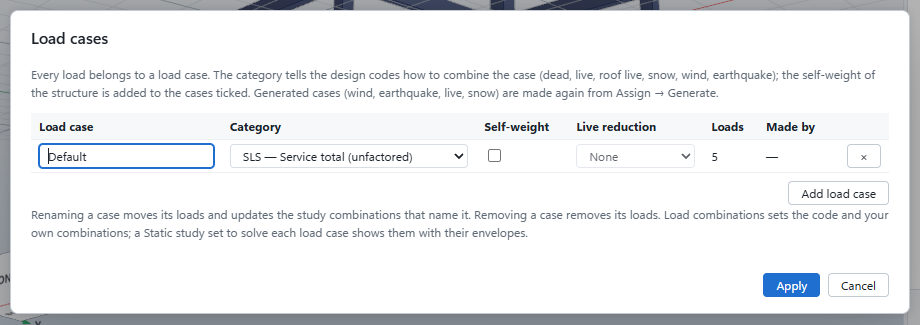
| Column | Meaning |
|---|---|
| Load case | The name, for example Dead, Live or Wind X |
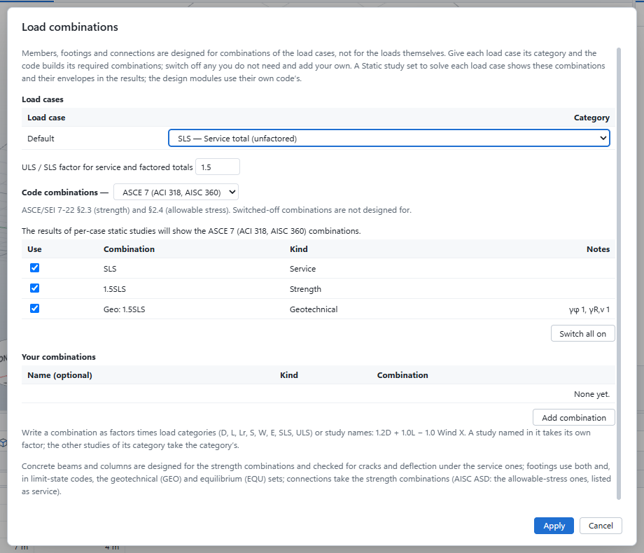
| Category | Dead (permanent) · Live (imposed) · Roof live · Snow · Wind · Earthquake · Notional (steel stability) · Service total (unfactored) · Factored total |
| Self-weight | Adds the self-weight of the model to this case |
| Live reduction | Live-load reduction by tributary area |
| Loads / Made by | How many loads the case holds, and whether you or a generator made them |
Click Add load case to add a case, then Apply. Renaming a case moves its loads with it; removing a case removes its loads.
Applying loads
Select the objects first, then choose a command from Assign › Loads. Each load dialog has a Load case field; typing a new name there creates a new case.
| Load | Applies to | Fields (defaults) |
|---|---|---|
| Force | Nodes, curves, surfaces | Magnitude (1000 N), Direction X/Y/Z (0, 0, −1) |
| Moment | Nodes, curves, surfaces | Magnitude (1000 N·m), Axis (0, 0, 1) |
| Line load | Curves | Load per length (10 kN/m), Direction, Per horizontal metre (projected) |
| Area load | Surfaces | Load per area (2 kPa), Direction, Per plan area (projected), Load panel distribution |
| Pressure | Surfaces, solid faces | Pressure, normal to the face |
| Temperature | Nodes, curves, surfaces, solids | Temperature change (°C) |
| Gravity | The whole model | Acceleration (9.81 m/s²) |
- A force on a curve or surface is a total, shared equally among its mesh nodes.
- Load panel distribution (One-way or Two-way) lets a floor without shells pass its area load to the edge beams.
- Options › Display › Loads shows or hides the load arrows.
Load generators
Assign › Generate makes code loads for you. Each generator first asks for the Code, then for its inputs. It remembers the inputs of the last run.
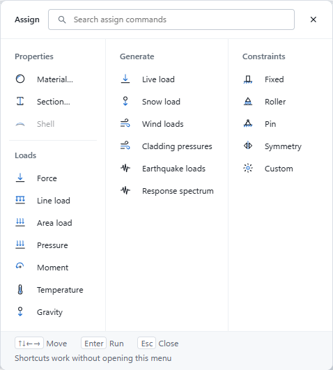
| Generator | Codes | Main inputs |
|---|---|---|
| Live load | ASCE/SEI 7-22 Table 4.3-1 · KDS 41 10 15 · EN 1991-1-1 Table 6.2 | Occupancy (gives the load from the code table), load case, load panel distribution, live load reduction by tributary area |
| Snow load | ASCE/SEI 7-22 Ch. 7 · EN 1991-1-3 · KDS 41 12 00 | Ground snow, Ce, Ct, Is, slippery roof; balanced, unbalanced, drift at a roof step, or sliding from an upper roof |
| Wind loads | ASCE/SEI 7-22 Ch. 27 · EN 1991-1-4 · KDS 41 12 00 | Basic wind speed, exposure or terrain category, factors (Kd, Kzt, Ke, G or Iw, GD), directions, roof uplift, enclosure, width across the wind |
| Cladding pressures | As for wind | Effective wind area, roof pitch; shows a table of zone pressures |
| Earthquake loads | ASCE/SEI 7-22 §12.8 · KDS 41 17 00 · EN 1998-1 §4.3.3.2 | SDS, SD1, TL, R, Ie (or agR, ground type, q for EC8); lateral system; accidental eccentricity; live-load share of the seismic weight. Makes the cases EQ X and EQ Y. |
| Response spectrum | As for earthquake | Makes a response spectrum study (see Part 2) |
Tip. Select the surfaces first for live and snow loads. Wind and earthquake loads use the whole model.
Load combinations
Define › Load cases › Load combinations shows the combinations the design code builds from your load-case categories, and lets you add your own. Part 3 explains this dialog in full, because the combinations drive the design.
Meshing
FEA Studio analyses a mesh made from your model. You do not have to build it yourself: the mesh is generated or updated automatically when you run an analysis. Still, you can control it and inspect it.
Mesh settings
Mesh › Generate › Settings
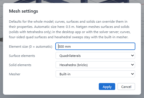
| Setting | Choices |
|---|---|
| Element size (0 = automatic) | A length; the note shows the automatic size |
| Surface elements | Quadrilaterals or Triangles |
| Solid elements | Hexahedra (bricks) or Tetrahedra |
| Mesher | Built-in or Netgen |
Curves, surfaces and solids can override these settings in their Properties, with their own element size, divisions or element shape. Mesh › Divisions… sets the number of elements per segment for the selected curves.
Note. The Netgen mesher works in the desktop app, or in the browser when the solver server is running. It meshes solids with tetrahedra only.
Mesh commands
| Command | Key | What it does |
|---|---|---|
| Generate mesh | Ctrl+M | Builds the mesh now (Esc cancels) |
| Refine mesh / Coarsen mesh | – | Halves or doubles the element size of the selection, or of the whole model |
| Clear mesh | – | Removes the mesh |
| Show mesh | – | Shows the mesh over the model (read-only) |
| Shrink, Mesh nodes | – | Display aids for checking the mesh |
The status bar shows Mesh: none, out of date or up to date. Click it to regenerate the mesh.
Mesh quality
Mesh › Inspect › Check quality opens the Mesh quality panel.
- Metric chooses the measure: Scaled Jacobian, Aspect ratio, Minimum angle, Maximum angle or Warpage.
- Grade chips show the counts of Good, Fair, Poor and Invalid elements. Click a chip to select those elements.
- A histogram, the minimum, mean and maximum, and a list of the worst elements are shown below.
- Quality map colours the elements in the 3D view by quality.
Locked models
Once a study has been solved, the model is locked so the results always match the geometry. You will see locked next to the project name and Locked in the status bar, and editing commands are greyed out.
To edit the model again, choose Results › Lock › Unlock model, or click Unlock model on the Results toolbar. Unlocking removes all result sets; analyse again after editing. Design objects such as beam lines, slabs and footings stay, but their checks become out of date.
Settings, shortcuts and help
Settings
Options › Workspace › Settings… contains:
- Theme: Use system setting, Light or Dark.
- Language: applies at the next start.
- Mouse navigation: the mouse layouts described in "Navigating the 3D view".
- Precise depth.
- Update feed URL and Check for updates at startup (desktop app).
Keyboard shortcuts
Help › Learn › Keyboard shortcuts lists every shortcut. The main ones are:
| Area | Shortcuts |
|---|---|
| File | Ctrl+N New · Ctrl+O Open · Ctrl+S Save · Ctrl+Shift+S Save as · Ctrl+P Report |
| Edit | Ctrl+Z / Ctrl+Y Undo / Redo · Ctrl+X Ctrl+C Ctrl+V · Ctrl+D Duplicate · Delete · Ctrl+A Select all · Ctrl+I Invert · Alt+Enter Properties |
| Drawing tools | N Point · L Line · A Arc · R Rectangle · P Push/pull · M Move · Q Rotate · S Scale · T Tape measure · Ctrl+G / Ctrl+Shift+G Group / Ungroup |
| Mesh and analysis | Ctrl+M Generate mesh · F5 Run analysis · Shift+F5 Cancel |
| View | F Fit all · Z Zoom to selection · W Zoom window · V Normal to · H Home · Shift+W Walk · 0 1 7 3 Views · 5 Orthographic · G Grid |
| Workspace | F1 Workflows · Alt or F10 Menus · Ctrl+E Explorer search · Ctrl+F1 Toolbars · F6 Next pane · Ctrl+Tab Next tab · Ctrl+F4 Close tab · Shift+F10 Context menu · F2 Rename |
Guided workflows
File › Workflows (F1) opens step-by-step guides with buttons for each step. Guides are available for concrete beams, concrete slabs and foundations.
AI assistants
Help › AI › AI assistants (MCP)… connects FEA Studio to an AI assistant that can read and edit the model through FEA Studio's tools. This works in the desktop app only.
Desktop and browser
FEA Studio runs as a Windows desktop app and as a browser preview. Modeling works the same in both, with these differences:
| Feature | Desktop app | Browser |
|---|---|---|
| Recent files | Yes | Not available |
| Save and export | Windows save dialog | The file is downloaded |
| Netgen mesher | Yes | Only with the solver server |
| Analysis | Built in | Needs the solver server |
| AI assistants (MCP) | Yes | Not available |
Checklist before analysis
Before you go on to Part 2, check that:
- Every member has a section and every shell a thickness and material. Realistic view makes gaps easy to spot.
- The model has supports. The Model stage must not say no supports.
- Every load is in a load case, and every case has the right category.
- The mesh is up to date, or you are happy for it to be built when you run.
- The project is saved (
Ctrl+S).