About this part
FEA Studio makes shop drawings directly from the model:
- steel members, plates and connections;
- the reinforced concrete beams, columns, slabs, walls and footings you have designed (Part 3).
Steel and concrete drawings are made together, as one numbered drawing set.
Note. The drawing set is always made fresh from the model as it is now. If you change the model or a design, make the set again. The set is not saved in the project file, but your sheet, title block and standard settings are kept.
Making a drawing set
Where to find it
- Drawings › Create drawings…. The Drawings menu appears once the model has results, when Simplified menus is on.
- Stage 7 Drawings in the Explorer: double-click Create drawings….
- The Create drawings… button in the empty Drawings panel.
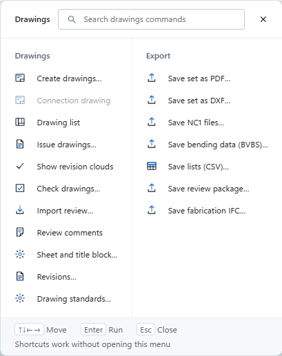
Besides making and exporting the set, the Drawings menu handles issuing and review:
| Command | What it does |
|---|---|
| Issue drawings… | Issues the set under a new revision: the drawings new or changed since the last issue take it, and their changes are clouded |
| Show revision clouds | Clouds what changed on each drawing since its last issue |
| Check drawings… | Finds what needs cleaning up before issue: text over text, lines through text, views running into each other or the title block, parts without dimensions |
| Save review package… | Saves the drawings as one HTML page that the engineer or fabricator opens in any browser to mark up, comment on and stamp each drawing |
| Import review… · Review comments | Brings the comments, markups and stamps back from a review file, shows them on the sheets, and lets you resolve and reply |
| Save fabrication IFC… | Saves the steel as IFC4 for fabrication: assemblies with their parts, holes and copes, bolts and welds, numbered and marked as on the drawings |
Steps
- Optional: select the members, connections, concrete beams, columns, slabs or footings you want. Only those will be drawn.
- Choose Drawings › Create drawings….
- Fill in the Create drawings dialog (see below) and click Create.
- A progress card titled Making drawings shows each stage, for example "Erection plans · Level 1 · 1 of 3". You can cancel it at any time.
- When it finishes, two things open:
- the Drawing tab, beside the 3D view;
- the Drawings panel, beside the Explorer.
The Output panel lists how many drawings, members, plates and bars were drawn, with any warnings.
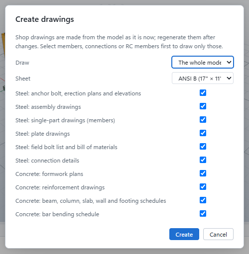
| Field | Choices |
|---|---|
| Draw | The whole model, or The selection |
| Sheet | ISO A4 landscape, ISO A3 (default), ISO A2, ISO A1, ISO A0, ANSI B (17" × 11"), ANSI D (34" × 22"), ARCH D (36" × 24") |
| Steel | Anchor bolt, erection plans and elevations · Assembly drawings · Single-part drawings (members) · Plate drawings · Field bolt list and bill of materials · Connection details |
| Concrete | Formwork plans · Reinforcement drawings · Beam, column, slab, wall and footing schedules · Bar bending schedule |
All the drawing kinds are ticked by default. Untick the ones you do not need.
What the set contains
Drawings are numbered by kind. Kinds that share a prefix share one number series.
| Prefix | Drawing | Contents |
|---|---|---|
| D0 | Drawing list | Number, title, type and location of every drawing; continues on D0A, D0B… |
| GN | General notes | Steel and reinforced concrete notes |
| E | Erection drawings | Isometric view; anchor bolt plan with a typical base detail; erection plan per level; elevation per braced grid line (alike grid lines share one) |
| E | Lists | Connection list; field bolt list with the bolt summary; field weld list (when chosen) |
| BM | Bill of materials | Every part with weight |
| CD | Connection details | One per kind of connection: elevation, plan, section and isometric views, with plate, bolt and weld marks and dimensions |
| B, C… | Assembly drawings | One per assembly mark: elevation, top and end views, sections, weld symbols and the part list |
| m, p | Single parts and plates | Members and plates nested on as few sheets as possible; members that differ only in length are tabulated |
| TD | Typical reinforcement details | Typical beam, column, slab, footing and wall details |
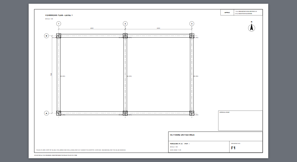
| F | Formwork plans | Slab outline, beams below, cut columns and walls, grids, and each member's R-drawing number. Alike floors share one plan (typ.). |
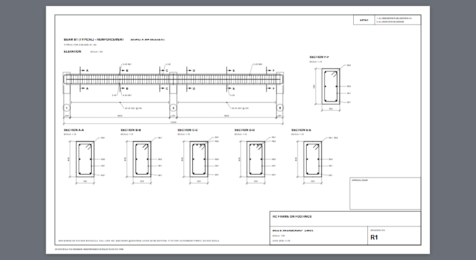
| R | Reinforcement drawings | Beams (elevation with sections), columns (elevation with laps and ties, section per storey), footings (plan and section), slabs (top and bottom bar plans) and walls. As many members per sheet as fit. |
| S | Schedules | Beam, column, slab, wall and pier, and footing schedules; the last one is the bar bending schedule (BS 8666) or bar list (ACI / CRSI) |
Identical members are drawn once and marked (typ.), for example "Beam B1, B2 - reinforcement (typ.)".
The Drawings panel and Drawing tab
Drawings panel
The Drawings panel lists the set by group: Index, List, Reinforcement, Bar schedule and so on. Each row shows a drawing number and title.
- Click a row to show that drawing.
- Use
↑↓HomeEndto step through the list.
The Explorer's Drawings stage shows the same set. Right-click a drawing there for Show drawing or Save as PDF….
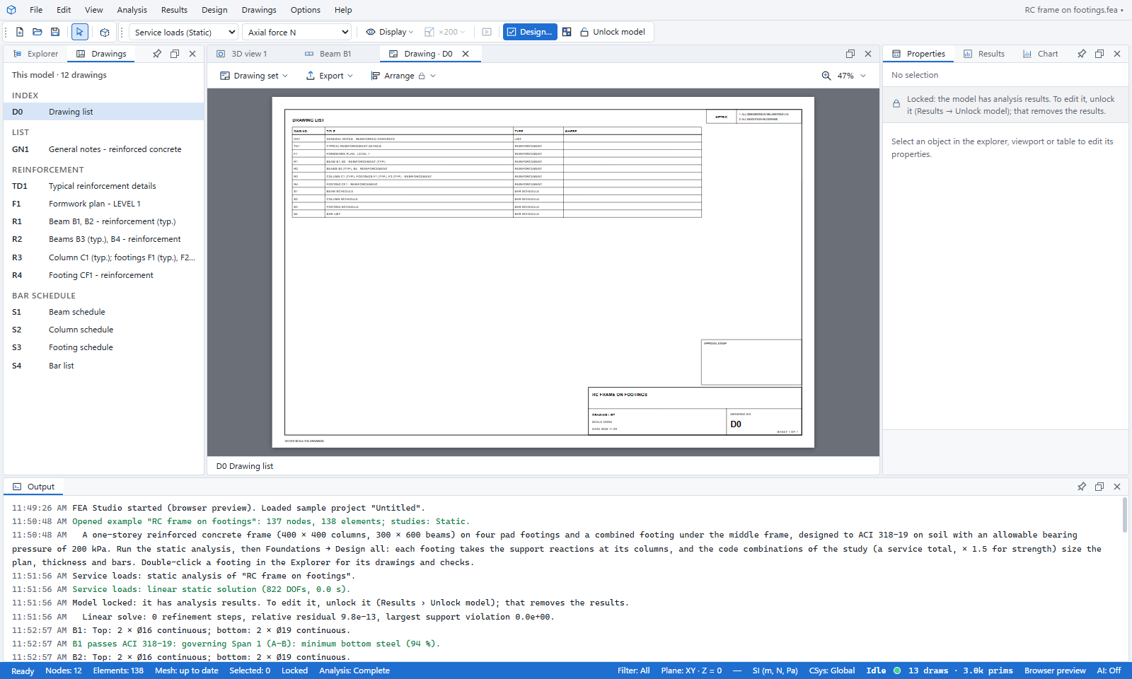
Drawing tab toolbar
| Menu | Commands |
|---|---|
| Drawing set ▾ | New set…, Regenerate, Sheet and title block… |
| Export ▾ | PDF (all drawings or this drawing), DXF (all sheets in a ZIP, or this drawing), Fabrication (NC1 files, bending data BVBS, bill of materials and bar schedule CSV), Print this drawing |
| Arrange ▾ | Align left / center / right / top / middle / bottom; Distribute horizontally / vertically; Align to sheet or Align selected views; Lock view positions |
| Zoom ▾ | Zoom in, Zoom out, Fit sheet, Fit width, 10 % to 800 % (100 % = actual paper size) |
Mouse and keys
| Action | How |
|---|---|
| Zoom | Mouse wheel, or + / − |
| Pan | Drag, or middle-drag anywhere |
| Zoom to a view | Double-click the view |
| Fit the sheet | Double-click empty paper |
| Previous / next drawing | ↑ / ↓ |
| Sheets of a multi-sheet drawing | Page Up / Page Down |
| Select all views | Ctrl+A |
| Clear the selection | Esc |
| Nudge selected views | Arrow keys: 1 mm, or 10 mm with Shift (views must be unlocked) |
Moving, scaling and aligning views
Views start locked: you can scale them but not move them. To move views, untick Arrange › Lock view positions.
- Move a view by dragging it.
- Scale a view by dragging its corner handle. It snaps to the nearest standard scale.
- Right-click a view to:
- pick a nearby standard scale;
- Zoom to view;
- Reset position and scale;
- Reset all views on this sheet.
- Select several views with
Ctrl+click,Shift+clickor aCtrl-drag box. Then use Arrange › Align or Distribute:- With one view selected, or with Align to sheet on, views line up with the sheet's drawing area.
- Distribute needs three views or more; the outer two stay put.
Your changes are kept when the set is regenerated, and they are used for print, PDF and DXF.
Sheet and title block
Drawings › Sheet and title block…
| Field | Choices or default |
|---|---|
| Sheet | ISO A3 by default |
| Units | Metric (mm) or Imperial (ft-in) |
| Projection | First angle or Third angle |
| Job number, Client, Fabricator | Text |
| Drawn by, Checked by, Approved by | Names for the title block |
| Legal owner (firm) | The firm that owns the drawings (ISO 7200) |
| Document status | Preliminary, For approval, Approved, Approved as noted, For fabrication, For construction, For erection, As built |
| Revision | Used until you keep a revision history (see below) |
These details go on every sheet. Saving the dialog regenerates the open set.
Note. Imperial drawings are usually third angle, and metric drawings first angle. The project region sets the default (see "Region and standard").
Revisions
Drawings › Revisions… keeps the revision history shown above every title block.
- The columns are Rev, Date, Description, By, Chk and App.
- Add revision fills in the next index, today's date and a description: "ISSUED FOR APPROVAL" for the first revision, "REVISED" for later ones. By, Chk and App come from the title-block names.
- Revisions are listed oldest first.
- Drawing standards › Revisions and numbering sets how many revisions are shown and whether the By / Chk / App columns appear.
Drawing standards
Drawings › Drawing standards… controls how every sheet is drawn. A preset sets about 150 options at once:
| Preset | Based on |
|---|---|
| ISO / Eurocode | EN 1090, ISO 2553, ISO 3766 |
| UK | BS EN, IStructE, BS 8666 |
| US | AISC, AWS, ACI 315 / CRSI |
| Thailand | ACI-based, TIS 24 |
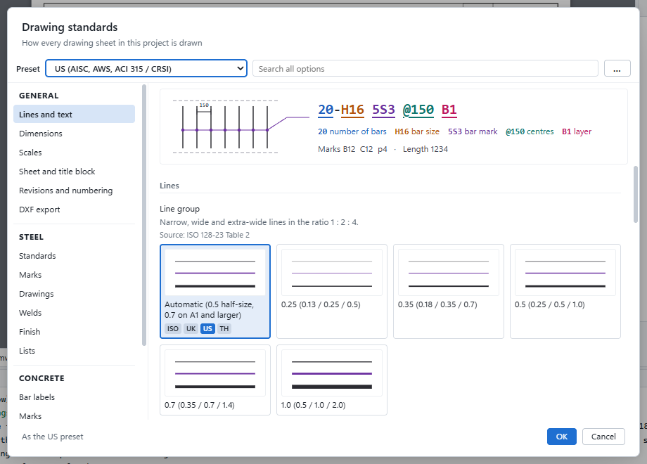
Using the dialog
- Pick a category on the left, or search all options with Search all options.
- Many options are picture cards. Each card shows how the choice looks on a sheet, and tags (ISO, UK, US, TH) show which presets use it.
- The preview at the top shows a slab plan and a bar call-up, coloured part by part.
- An option you change is shown in bold, with the preset value and a Reset link. The footer counts how many options differ from the preset.
- The … menu offers:
- Reset all to the preset;
- Export standard…, which saves your office standard as a file;
- Import standard…, which loads one.
Categories
| Category | Main options |
|---|---|
| Lines and text | Line group (pen widths), wide or narrow outlines, hidden lines, bar line weight, black or colour by role, text height, letter case |
| Dimensions | End marks (oblique strokes, arrows, dots), text direction, decimal mark, imperial precision and format |
| Scales | Scale bar, preferred scales, scale range per view kind (for example connection details 1:5–20, erection plans 1:50–200) |
| Sheet and title block | Layout (Compact or ISO 7200), logo, extra rows, margins, grid reference zones, projection symbol, "Do not scale", approval stamp, protection notice |
| Revisions and numbering | Revision index (letters, numbers, P1…C1), revisions shown, drawing number prefix, digits, prefix per kind |
| DXF export | Layer names (by line weight, by role, ISO 13567, US National CAD Standard), DXF version (R2000 or R12) |
| Steel: Standards | Steel standards, execution class, bolt tightening, slip class, extra field bolts, holes, AESS, grout, levelling, extra notes |
| Steel: Marks | Assembly and part prefixes, case, numbering, opposite hands |
| Steel: Drawings | Running or chain dimensions, NS / FS marks, hole call-outs, grade on parts, column faces, slopes |
| Steel: Welds | Weld symbol standard (AWS A2.4, ISO 2553 A or B), fillet size, tail, CJP welds, inspection symbols, field welds, quality level |
| Steel: Finish | Surface preparation, coating, dry film thickness, corrosivity category |
| Steel: Lists | Net or gross weights, bill of materials columns |
| Concrete: Bar labels | Call-up template (for example 20H16-03-150 B1 or 12-#5 5S3 @300 T1), bar size notation, centres, layer codes |
| Concrete: Marks | Mark style, straight bars marked, numbering per member or through the job |
| Concrete: Graphics | How sets of bars are drawn on plans, far-face bars, bar-end strokes, cover dimensions |
| Concrete: Views and scales | Separate or combined slab plans, which members are drawn one by one, fitted or fixed scales |
| Concrete: Schedule | BS 8666 or ACI / CRSI bar list, mass column, cut-length method and rounding, stock length |
| Concrete: Notes | First link position, anchorage and lap table, layer notation sketch, extra notes |
Click OK to apply the changes. An open set is regenerated.
Region and standard
The project region (Part 1) picks the default preset, sheet and projection:
| Region | Preset | Sheet | Projection |
|---|---|---|---|
| United States, Canada | US | ANSI B | Third angle |
| Korea | ISO | ISO A3 | Third angle |
| Philippines | US | ISO A3 | Third angle |
| Australia | UK | ISO A3 | Third angle |
| Europe, India, China | ISO | ISO A3 | First angle |
The units follow the project, so US units give imperial drawings. Your changes to sheet, units, projection and standard are remembered for each region. The title-block names are shared by all projects. The Thailand preset has no region of its own; choose it in Drawing standards.
Connection drawings
You can draw one connection on its own, without making the whole set:
- Select a connection and choose Drawings › Connection drawing.
- Or right-click a connection and choose Connection drawing.
- Or click Drawing in the connection editor.
The drawing shows views, dimensions, bolts, welds and the connection's parts.
Export and print
| Output | Command | Result |
|---|---|---|
| Drawings › Export › Save set as PDF…, or Export ▾ › PDF | One page per sheet at its own paper size; the whole set or one drawing | |
| Export ▾ › Print this drawing | The system print dialog | |
| DXF | Save set as DXF… | One DXF file per sheet, in a ZIP; AutoCAD R2000 by default, or R12 (see DXF export in Drawing standards) |
| NC1 | Save NC1 files… | DSTV NC1 files per part, plate DXF outlines and the bill of materials, in a ZIP |
| BVBS | Save bending data (BVBS)… | Bar bending data for bending machines (.abs) |
| CSV | Save lists (CSV)… | Bill of materials and bar bending schedule, in a ZIP |
Default file names start with the project name, for example "Project - drawings.pdf". In the desktop app, a bar appears after each save with Open folder and Open file.
Note. In the browser version, PDF output goes through the print dialog: choose "Save as PDF" as the printer. Shop drawing sheets are not exported to Word.
Drawings in the design tabs
The concrete beam, column, slab and steel member tabs (Part 3) draw their own 2D elevations, sections and plans. Use their Print, PDF and Word buttons to print a member's drawings together with its checks. Footing calculation reports include a Drawings section with the plan and section.