Bridge pushover and earthquake time history, on OpenSees
Make a bridge from a template, change its girders, bearings and piers one by one, then push each bent and shake the whole bridge with the OpenSees you have installed. Every bent is checked for displacement capacity and ductility.
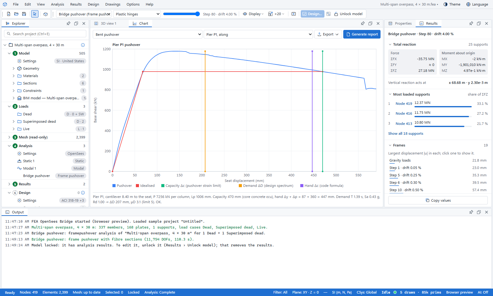
From a bridge template to a checked seismic response
Templates
Girder, box, truss, arch, cable-stayed and suspension bridges from a few parameters, with load cases and studies ready to run.
Components
Change one girder, diaphragm, bearing, pier or abutment, or every similar one, and copy a change to the others.
Linear analysis
Linear static, modal, linear dynamic, nonlinear static and response spectrum, all on OpenSees.
Bridge pushover
Pier columns as RC fibre sections with confined concrete. Each bent is pushed along and across the bridge.
Time history
Nonlinear earthquake time history with bearings, abutment backfill and shear keys, and multi-support excitation.
Capacity check
Displacement capacity against demand, ductility and P-Δ for every bent, to the AASHTO Guide Spec or Caltrans SDC 1.7.
OpenSees is installed by you. FEA OpenSees Bridge writes the model as an OpenSees input script and runs the OpenSees.exe you installed yourself. It doesn’t include, install or download OpenSees. OpenSees is distributed by the Regents of the University of California under its own licence: free for educational, research and non-profit use, while commercial use may need a licence from UC Berkeley. How to set it up.
Steel and RC member design, footings, connection hand checks, drawings and IFC exchange come from FEA Studio. Building templates, slabs, walls and building seismic studies are in FEA OpenSees Building.
Six template families
Choose one in File › New… and set its parameters. Each makes members, supports, load cases and studies.
Girder bridges
Eight girder bridges, from a single span to a 270° ramp, with PSC girders, RC beams, steel plate girders, a box or a solid slab, on piers and abutments. Also a continuous plate girder bridge with cross-frames, skew and plan curvature.
Box girder bridge
A continuous concrete or steel-and-slab box of shell plates, one or two cells, constant depth or haunched over the piers.
Truss bridge
Pratt, Howe, Warren or Warren with verticals; through or deck; floor beams, stringers and lateral bracing.
Tied arch bridge
Parabolic ribs and tie girders, vertical or network hangers, wind bracing and an optional rib inclination.
Cable-stayed bridge
One or two H, A or single-column pylons with fan, harp or semi-fan stays and optional auxiliary piers.
Suspension footbridge
Parabolic main cables, portal towers, backstays, hangers and a stiffened deck.
Edit the bridge part by part
The girder bridges are built as a BIM model and converted to the analysis model. Click a part in the 3D view and change it in the Template panel.
Girders
A section from the library of 92 AASHTO, Caltrans and WSDOT girders, its dimensions and end blocks, or the plates of a steel girder.
Diaphragms
Present or not, thickness and depth, for intermediate, end and pier diaphragms.
Bearings
Pot (fixed, guided along, guided across, free) or elastomeric, with plan size and height.
Piers
Single, multiple or wall columns, pile bents and flared columns; seven column shapes, the bent cap and the foundation.
Abutments
Front wall, footing, back wall, wing walls, approach slab and optional piles.
Scope and copy
Apply a change to this one, the same line in every span, a whole span or every one, and copy it to the similar ones later.
One model, eight stages
The Explorer lists the project as numbered stages and shows which ones are out of date.
Model
A bridge template, its alignment and its components.
Loads
Self-weight, surfacing and lane loads from the template; ground motions.
Mesh
The analysis model, converted from the BIM model.
Analysis
Five linear and nonlinear types, plus bridge pushover and time history.
Results
Deformed shapes, member forces, bent pushovers and the capacity check.
Design
RC and steel members, footings and connection hand checks.
Drawings
Reinforcement and steel shop drawings.
Reports
The bridge seismic report as PDF, Word or HTML.
Learn FEA OpenSees Bridge step by step
Six tutorials on one overpass, from the template to the bent-by-bent check.
A girder bridge from a template
Make a multi-span overpass, set its spans and girders, and run the modal and static analyses.
Start →Edit components one by one
Change one girder, every girder of a line, or a whole pier, then copy the change to the similar ones.
Start →Bearings and abutments
Choose bearing types, and set how the seismic studies model bearings, backfill and shear keys.
Start →Pier pushover with fibre sections
Run a bridge pushover and read each bent’s moment–curvature and pushover curve.
Start →Time history with multi-support excitation
Add a ground motion and shake the bridge, with the record arriving later along it.
Start →The AASHTO / Caltrans capacity check
Check every bent along and across, read the charts and make the bridge seismic report.
Start →The FEA OpenSees Bridge manual
One page from install to limitations, with the parameters and study properties in tables.