About this part
This part continues from a solved static study (Part 2). It explains how FEA Studio designs the structure to the codes you chose, and how to read the results.
Design always works from load combinations of the analysis results. The usual order is:
- Set the design codes: the project region (Part 1) or each module's settings.
- Give every load case its category and check the load combinations.
- Solve a Static study with Solve: Each load case.
- Run Design › Design… to design everything at once, or design one family or one member at a time.
- Read the verdicts: the Design summary, the D/C ratios in 3D, and each member's tab.
- Adjust and design again, then produce drawings (Part 4) and reports (Part 5).
What can be designed
| Family | Design objects | Codes |
|---|---|---|
| Concrete beams | Beam lines (continuous over supports) and their spans | ACI 318-19, KDS 14 20, NSCP 2015, EN 1992-1-1 (with national annexes), CSA A23.3-19, AS 3600-2018, IS 456:2000, GB 50010-2010 |
| Concrete columns | Column stacks (base to roof) and their storeys | As for beams |
| Concrete slabs | One-way, two-way, flat slabs and plates, ribbed and waffle slabs | As for beams |
| Shear walls | Piers and spandrels (by label) | ACI 318-19 / 318-25, NSCP 2015, KDS 14 20, KBC 2016, EN 1992-1-1, AS 3600, CSA A23.3-19 / -24, IS 456, GB 50010 |
| Concrete shells | Any concrete surface (sandwich model) | EN 1992-1-1 |
| Steel members | Beams, columns and braces | AISC 360-22 LRFD / ASD, KDS 14 31 10, EN 1993-1-1, CSA S16-19, AS 4100:2020, IS 800:2007, NSCP 2015 |
| Steel joists | K, LH and DLH joists | SJI 100-2020, SJI-2010 |
| Composite beams and columns | Steel beams acting with the slab; encased and filled columns | AISC 360, KDS 14 31 80, NSCP 2015 §509, EN 1994-1-1, CSA S16, IS 11384 |
| Floor vibration | Bays of composite floors | AISC Design Guide 11 |
| Footings | Pad, combined and strip footings | ACI 318-19 / ASCE 7-22, KDS, NSCP 2015, EN 1992 / EN 1997, CSA / NBCC, AS 3600 / AS/NZS 1170, IS 456 / IS 6403, GB 50007 / GB 50010 |
| Steel connections | Shear, moment, base, bracing and splice connections, checked by CBFEM | KDS 14 31 25, AISC 360-22 LRFD / ASD, NSCP 2015 §510, EN 1993-1-8, CSA S16-19, AS 4100-2020 |
Caution
The steel joist capacities in this version are placeholder sample values with SJI-style names. They are not the SJI load tables, so do not use them for design until licensed SJI tables are installed.
The Design menu
The Design menu holds the one-button design and one sub-menu for each design family.
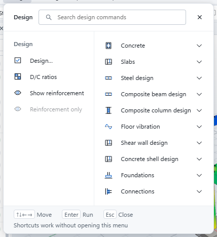
| Command | What it does |
|---|---|
| Design… | Designs the whole model in one go. Available after a static or nonlinear analysis. |
| D/C ratios | Colours every designed member, slab, wall and footing by its demand/capacity ratio (red above 1.00) |
| Show reinforcement | Draws the designed bars, stirrups, ties and meshes in 3D, with the concrete shown translucent |
| Reinforcement only | Hides the model and shows only the bars |
| Concrete, Slabs, Steel design, Composite beam design, Composite column design, Floor vibration, Shear wall design, Concrete shell design, Foundations, Connections | The design families, each with its own create, setup, design and display commands |
Design objects also appear under stage 6 Design in the Explorer. Each item shows its verdict and utilisation, for example ✓ 94 % or ✗ 112 %. A dot after the value (✓ 94 % ·) means the check is out of date.
Codes, combinations and bar sizes
Design codes
The codes come from the project region and the codes you picked in File › New (Part 1):
- The concrete code sets the code for concrete beams, columns, slabs, walls and footings.
- The steel code sets the code for steel members, connections, and composite beams and columns.
You can change a family's code later in its settings, for example Design › Concrete › Setup › Design code. When you change a concrete code:
- strengths and cover reset to the new code's usual values;
- existing bars move to the nearest sizes of the new code.
For Eurocode 2, choose the National Annex: CEN recommended values, United Kingdom, Ireland, Singapore, Germany, Denmark, Finland, Norway, Poland, Portugal, Slovenia, Bulgaria, Italy or Sweden.
Load combinations
Members, footings and connections are designed for combinations of the load cases, not for the loads themselves.
- Give each load case its category.
- The code builds its required combinations from those categories.
- Switch off any combinations you do not need, and add your own.
Open the dialog from Define › Load cases › Load combinations, from Design › Settings › Load combinations… in the Explorer, or from any module's Load combinations command. All modules share the same set.
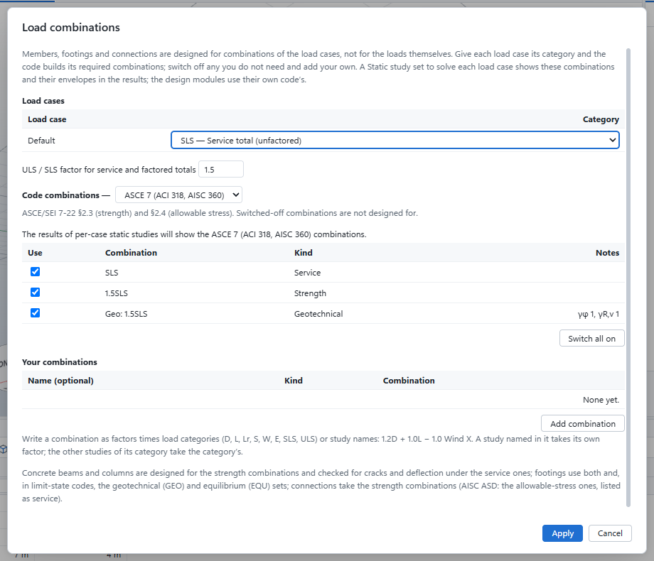
Load cases. Give each case a category:
- D Dead (permanent)
- L Live (imposed)
- Lr Roof live
- S Snow
- W Wind
- E Earthquake
- N Notional (steel stability)
- SLS Service total (unfactored)
- ULS Factored total
ULS / SLS factor. This factor converts a study that is already a total:
- a service total is multiplied by it for strength design;
- a factored total is divided by it for service checks.
Code combinations. Choose the combination standard:
- ASCE 7 (ACI 318, AISC 360)
- KDS (Korea)
- Eurocode (EN 1990)
- NBCC (CSA)
- AS/NZS 1170
- IS 456 / IS 875
- GB 55001 (China)
- NSCP 2015 (Philippines)
The table lists every combination with its Kind (Strength, Service, Geotechnical or Equilibrium) and notes. Untick Use to leave a combination out of the design, and click Switch all on to restore them all.
Your combinations. Click Add combination and write factors times categories or load case names, for example 1.2D + 1.0L − 1.0 Wind X. Set the Kind to Strength or Service.
| Module | Uses |
|---|---|
| Concrete beams and columns | Strength combinations for design; service combinations for crack and deflection checks |
| Footings | Both, and in limit-state codes also the geotechnical (GEO) and equilibrium (EQU) sets |
| Steel connections | Strength combinations (AISC ASD: the allowable-stress ones) |
| Steel, walls, composite, joists | The code's own combinations, or a family chosen in their settings |
Tip. You can change the combinations after the analysis. The combined results are rebuilt at once, and you only need to design again.
Rebar sizes
Rebar sizes (Design › Concrete, Slabs or Foundations › Setup) sets the smallest and largest main bar the design may use. Stirrups and ties keep their own size.
| Member | Smallest | Largest |
|---|---|---|
| Beams | 16 mm | 32 mm |
| Columns | 16 mm | 32 mm |
| Footings | 16 mm | 40 mm |
| Slabs | 10 mm | 20 mm |
The bar lists follow the current code, for example D16 or #5. The design tries the sizes from the smallest up until the requirements are met.
One-button design
Running Design…
- Solve a static study (Part 2). Design… stays greyed out until one has results.
- Choose Design › Design…, or click Design… on the Results toolbar.
- The Design dialog lists each family the model has, with what will be designed or made. For example: "5 beam lines to make", "6 column stacks to make", "5 footings". Untick any family you want to leave out. Everything ticks or unticks them all.
- Click Design.
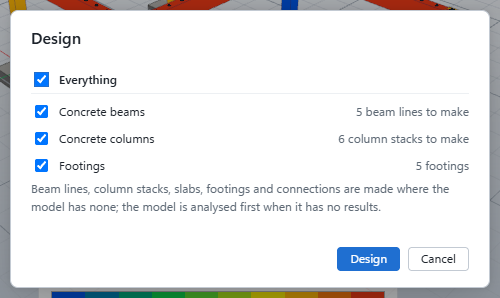
Families are designed in this order:
- Steel members
- Composite beams and columns
- Concrete slabs
- Concrete beams
- Concrete columns
- Shear walls
- Concrete walls and shells
- Footings
- Steel connections
Steel comes first, because changing sections changes the forces. Columns come after beams, because the strong-column / weak-beam check needs the beam bars.
Each step shows a progress card with Cancel. Cancelling stops that step, and the steps after it do not run.
What is made automatically
Before designing, Design… creates the design objects the model is missing:
| Family | Created where missing |
|---|---|
| Concrete beams | A beam line along every chain of level concrete beams |
| Concrete columns | A column stack (C1, C2…) along every chain of vertical concrete columns |
| Concrete slabs | A slab over every group of level shells and every load-panel floor |
| Shear walls | A pier label (P1, P2…) for every wall plane; panels that share edges are joined |
| Footings | A strip footing under every concrete wall, and a pad under every other support |
| Steel connections | A fin plate at every free steel joint, or a moment connection where the analysis held the end rigid; base plates at column feet, plus splices and gussets |
Only members that carry loads are designed. Footings with no reaction at their support are skipped, and a note says so.
The Design summary
When the run ends, the Design summary opens:
- Banner: "Every member passes. 0 failures across N groups.", "N members still fail…", or a note that a step stopped with an error.
- Table: each group with the number designed (and how many are new) and the number of failures.
- Report… opens the Design report (Part 5).
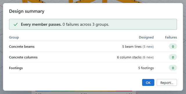
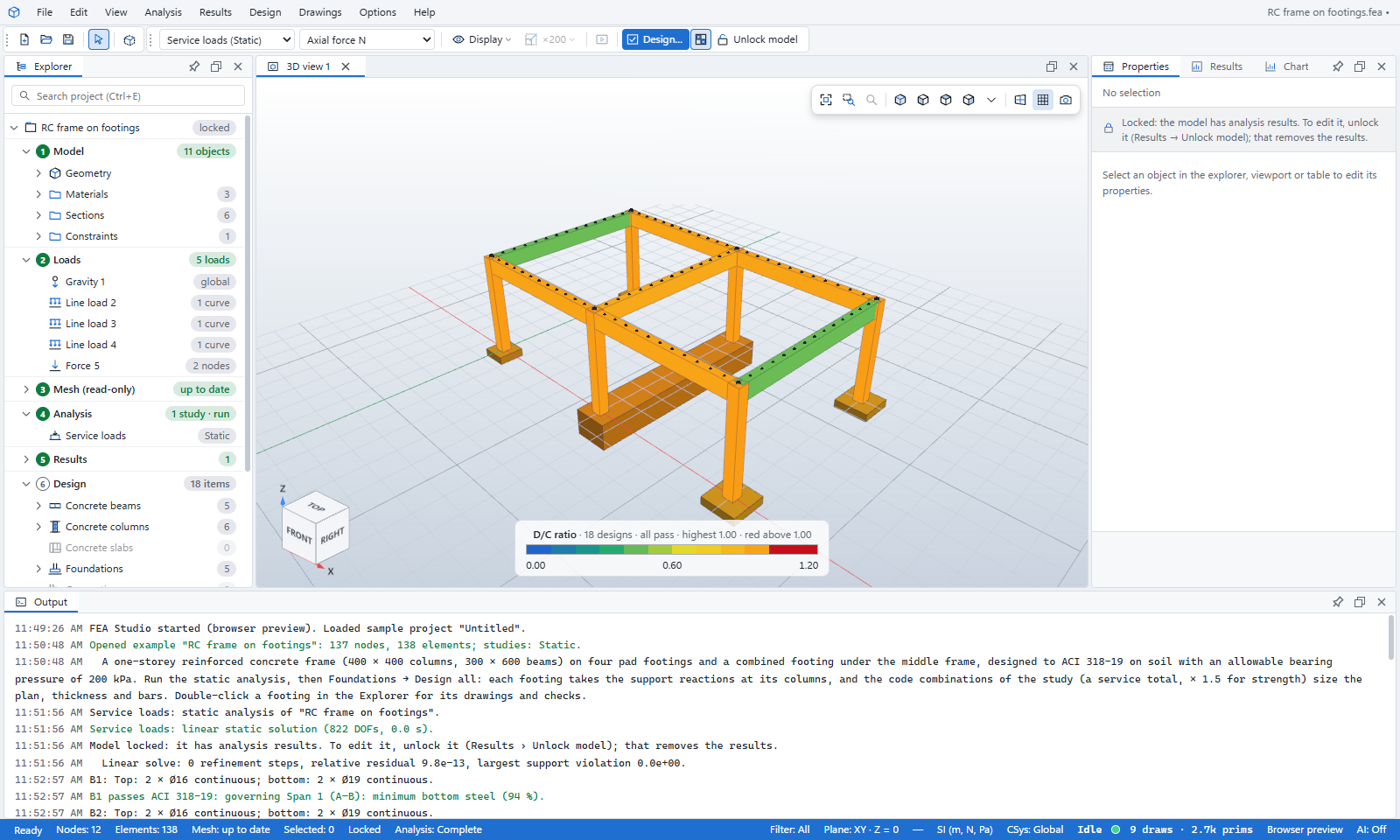
The D/C ratio view switches on behind the summary.
Reading the design
D/C ratios in 3D
Design › D/C ratios colours every design on one scale: steel and composite members, concrete beam spans, column storeys, slabs, wall piers, shells and footings.
- The legend reads D/C ratio, followed by the number of designs, whether all pass, and the highest value.
- The scale runs from 0 to 1.20 in 12 bands. It goes from blue to orange up to 1.00; only values above 1.00 are red.
- A member's own result wins over its group's: a span over its beam line, a storey over its stack.
- Objects that have not been designed keep their normal colour.
- Picking another result, frame or animation turns the D/C view off.
Verdicts
| Wording | Meaning |
|---|---|
| ✓ Passes · 87 % | The highest utilisation is 87 % of capacity |
| ✗ Fails · 112 % | At least one check exceeds its limit |
| governing: … | The controlling check and combination |
| (out of date) or a trailing · | The model, loads or settings changed since the check; check again |
| Trial bars, not designed | A concrete object was made but not designed yet; the Explorer badge says trial |
| Not checked | No check has run |
Each check row reads ratio = demand / capacity, with the code clause and a note. Rows over their limit are marked ✗.
Member tabs
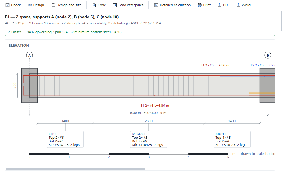
Double-click a design object in the Explorer (or use the family's … tab command) to open its tab in the centre. The tabs share a common toolbar:
- Check checks the member as it is.
- Design chooses bars or sections.
- Code and Load categories (or Settings) open the setup dialogs.
- Detailed calculation shows the step-by-step equations.
- Print, PDF and Word export the tab.
In Properties, every designed member also has a Calculation sheet box. Tick it to open the member's tab.
Reinforcement in 3D
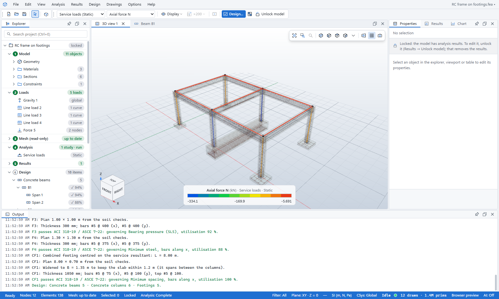
Design › Show reinforcement draws the designed bars of every concrete member:
- beam bars and stirrups;
- column bars and ties;
- slab meshes;
- wall bars;
- footing mats.
The concrete is drawn translucent. Reinforcement only hides everything except the bars.
Concrete beams
Beam lines
A beam line is a continuous chain of level concrete beams over columns, walls and supports. Each part between two supports is a span with its own section and bars. The bars are designed for the whole line, so every span fits its neighbours:
- continuous top and bottom bars run along the line;
- added top bars sit over each support;
- added bottom bars sit in each span;
- stirrup zones are set span by span.
Create:
- Design › Concrete › Beam line makes a line from the selected beams.
- Auto beam lines makes one along every chain. Design… does this for you.
Concrete settings
Design › Concrete › Setup › Design code opens Concrete beam design. Beams, columns and slabs share these settings:
| Setting | Notes |
|---|---|
| Design code, EN 1992 National Annex | See "Design codes" |
| Concrete f'c / fck (fcu,k for IS and GB) | Concrete strength |
| Longitudinal bars fy · Stirrups fyt | Steel strengths |
| Clear cover to the stirrups · Largest aggregate | Used for spacing and anchorage |
| Stirrup diameter (start) · Bar layers allowed (1 or 2) · Stock bar length | Detailing |
| Deflection limit: span / … · Crack width limit (EC, IS, GB) | Serviceability |
| Sustained part of the live load ψ2 · Sustained part of a service total | Long-term deflection |
| Seismic detailing | None (gravity / wind frames), Intermediate moment frame, Special moment frame |
| Columns: biaxial bending | The code's method, or Exact (strain compatibility, inclined neutral axis) |
| Columns: creep coefficient φ | Default 2 |
| Slabs act as flanges (T / L beams) | On by default |
The beam line tab
The tab shows the verdict, then these panels:
- Elevation: the beam with every bar labelled.
- Sections: the cross-sections along the beam.
- Moment, shear and deflection: charts of the moment envelope against the strength, the design shear against the resistance, and the long-term deflection.
- Code checks: each check with its combination, utilisation and clause.
- Spans: one row per span, with Design span and Suggest…. Suggest offers bar sets that keep the neighbouring spans as they are.
- Supports and continuous bars: the added top bars over each support and how far they run.
- Bar schedule, Combinations, Loads, Warnings and Detailed calculation.
The toolbar has Check, Design (bars and stirrups of the whole line) and Design and size. Design and size does the same as Design and also deepens spans whose section is too small.
Edit beam… changes one span:
- section: width, depth and flange;
- bars: added bottom bars and their cut-off points;
- stirrups: bar, legs, and spacing in the middle and in each end zone;
- side bars;
- Keep when designing (lock), which keeps your choice when you design again.
By default the beam uses the model results. In Loads you can choose Enter span loads instead, and turn Pattern loading on or off.
Checks:
| Group | Checks |
|---|---|
| Flexure | Sagging and hogging strength, ductility (c/d), minimum and maximum steel, axial compression |
| Shear and torsion | Shear strength, stirrup spacing, minimum stirrups; torsion section, closed stirrups, longitudinal bars |
| Detailing | Bar layers and clear spacing, hook anchorage into supports, top bars past the inflection point, bottom bars into the supports, at least two continuous bars |
| Seismic | Steel ratio, strength at the face and along the span, hoop zones, continuous bars |
| Serviceability | Crack control (by spacing, steel stress or crack width, depending on the code) and deflection |
Design › Concrete › Design › Summary lists every beam line with its continuous bars, utilisation and verdict.
Concrete columns
Column stacks
A column stack runs from the base to the roof.
- Bars and ties are designed from the top storey down. A lower storey never has fewer bars than the one above.
- Bars are lapped just above each floor, or at mid-height for special moment frames. A T marks a tension lap.
- Rectangular and circular columns are supported, with ties or a continuous spiral.
Create: Design › Concrete › Column stack (from the selected columns) or Auto column stacks.
The column tab
- Storeys: bars and ties of each storey.
- Frame and slenderness: the stiffness at the top and bottom joints, and the slenderness against the code limit. A storey is treated as sway when its stability index exceeds the code limit.
- Interaction (P–M) of each storey: the interaction diagram. Show Mh–Mb contour shows the biaxial moment contour at the governing axial force.
- Storey table, Code checks, Bar schedule and Warnings.
Lengths opens Effective lengths:
- For each bending direction, choose Automatic (stability index), Braced (non-sway) or sway.
- You can set k yourself. Otherwise it comes from the alignment chart, using the column and beam stiffness at both joints.
Checks:
- Strength: axial force with biaxial bending; the largest axial compression.
- Slenderness: about each axis.
- Detailing:
- minimum and maximum steel;
- number of bars and clear spacing;
- continuity with the storey below;
- laps;
- bars hooked into the roof.
- Shear: along each axis.
- Spirals and ties: pitch, spiral ratio, tie spacing and hoop zones.
- Joints: strong column / weak beam, and joint shear.
Concrete slabs
Slab kinds
The Kind in Properties is Automatic (from the supports) by default. You can set it to One-way, Two-way, Flat slab / plate or Ribbed / waffle.
Create: Design › Slabs › Slab (from selected level shells) or Auto slabs.
Note. Floors drawn as load panels, rather than shells, have no slab moments from the analysis. FEA Studio asks before designing them by the code's method: moment coefficients or direct design between beams. Model irregular floors as concrete shells instead.
Slab settings
Slab settings (dialog Concrete slab design) holds:
- concrete and bar strengths;
- clear cover and largest aggregate;
- the deflection limit (flat panels use the diagonal span);
- the crack width limit;
- the sustained live-load part ψ2.
Further setup commands:
- Moments… chooses whether design moments come from the Shell model or from the Code's coefficient method. For the coefficient method it also asks for the superimposed dead and live loads.
- Ribs… sets one-way or waffle ribs: rib width, spacing, total depth, topping, and solid heads at columns. Set the shells to the ribs' stiffness updates the analysis model; re-mesh and solve again afterwards.
- Drop panels… adds drop panels at one column or at every column of the slab, with their size and depth.
The slab tab
Design chooses:
- the bottom and top meshes;
- bands over the supports and in the panels;
- punching shear studs at the columns.
The tab shows:
- Plan and Reinforcement, where you can add or edit bands;
- Panels and Design strips;
- Punching at the columns;
- Deflection;
- Code checks, Combinations, Bar schedule, Warnings and Detailed calculation.
The checks cover flexure, punching, deflection and crack control.
Shear walls and concrete shells
Piers and spandrels
Walls are designed by label:
- Assign pier label… groups wall surfaces into one pier. The pier is cut at the top and bottom of each storey, and angled legs make a flanged pier.
- Assign spandrel label… marks coupling beams over openings, one per level.
Design… labels unlabelled walls as piers for you.
Design settings… (dialog Shear wall design settings):
| Setting | Choices |
|---|---|
| Design code · Load combinations | See the table at the start of this part |
| Pier design method | Simplified C & T (edge members, planar piers only), Uniform reinforcing (P-M-M), General reinforcing |
| Uniform reinforcing | Check the reinforcement given (D/C), or Design the steel ratio (D/C = 1) |
| Bars | Bars along the faces (diameter, spacing), end bars, cover to the bar centres |
| Ductility (seismic combinations) | Ordinary, Intermediate / moderately ductile, Special / ductile |
| Seismic shear amplification | On or off |
Each pier or spandrel can override these settings in Properties, or be excluded from the design. Spandrels can have diagonal reinforcement (ACI 318 §18.10.7).
Show labels, Show D/C and Show wall bars display the results in 3D. The Pier / spandrel sheet gives the checks station by station.
Concrete shell design
Design › Concrete shell design designs any concrete surface by the EN 1992-1-1 sandwich model, element by element. The settings are:
- one or two layers of bars;
- covers;
- bar directions;
- cot θ of the shear links.
Choose a contour to see where steel is needed: Show As bottom / top, direction 1 / 2. Elements that need too much steel are flagged as overstressed. Surfaces covered by slabs or wall labels are left out unless you tick Also RC slabs and labelled walls.
Steel members
Every steel curve is a design member. Merge as one member joins collinear curves into one design member, and Split member separates them again.
Steel design settings
Design › Steel design › Setup › Design settings… opens Steel design settings.
| Setting | Choices or default |
|---|---|
| Design code · Load combinations | The code's own combinations, or a family |
| Second-order effects | None (forces as analysed); Member amplification only (B1 / δb); Member and storey sway amplification (B1 and B2 / αcr) |
| Notional loads | On or off, with a coefficient (0 = the code default) |
| Effective length factors of columns | K = 1 (direct analysis method), or From the joints (alignment charts) with Braced or Sway frames |
| Ratio limit | 1.0 |
| Deflection limits | Live load L/360, total load L/240, cantilevers by the 2L rule |
| Deflection counts in the member ratio | Off |
| Iterated auto-design: most rounds | 5 (at most 20) |
| EC3 and AS 4100 options | Interaction factors (Annex A or B), lateral-torsional buckling method, kt / kl / kr |
Checking and auto-design
- Check all and Check selected check the sections as they are.
- Design all… and Design selected… open Steel auto-design. It lists each member with its current section, the proposed section and the ratio. Then:
- Apply sets the new sections.
- Apply and analyse sets them and re-runs the analysis.
- Iterate repeats design and analysis until the sections stop changing.
- Storey sway… lists drift, storey shear and the sway amplification of each storey.
- Clear results removes the checks.
Per-member settings in Properties:
- Designed as: beam, column or brace.
- Cantilever.
- Lengths and factors: Ly, Lz, Lb, Ky, Kz, Cb.
- Design group: every member of the group gets the same section.
- Series / sections: the sections to choose from, for example "W, IPE, HEA".
- Keep the section (check only).
The Member sheet shows:
- the member and its section;
- the forces along the member;
- every check for the governing combination;
- the detailed calculation.
Joists
Assign joist designs the selected beams as SJI joists (K, LH or DLH series), with their own settings and checks. Read the caution at the start of this part before using joist results.
Composite beams and columns
Design settings… (dialog Composite design settings) holds:
- Codes: the beam and column codes, and the load combinations.
- Every steel beam under a slab is composite: detects composite beams automatically.
- Construction stage: superimposed dead load cases, construction live load and shoring.
- Deck: rib height, width and spacing, concrete above the ribs, and rib direction.
- Studs: diameter, height and strength.
- Least composite action: 25 %.
- Deflection and camber: limits, and automatic camber at 80 % of the dead-load deflection.
- Floor vibration: the AISC DG11 walking check, with damping and occupancy.
Commands:
- Make composite and Make non-composite choose which beams are composite.
- Check all beams checks every composite beam.
- Design sections… picks the lightest steel sections that pass, then re-analyses.
- Make composite column… sets a column as encased or filled; Check all columns checks them for axial force and bending.
The checks cover:
- strength;
- minimum composite action;
- concrete and bottom-flange stress in service;
- deflection.
Floor vibration › Vibration results… lists the natural frequency and peak acceleration of each bay.
Footings
Footing types
| Type | Placed |
|---|---|
| Pad footing (isolated) | One per selected column node |
| Combined footing | Under two or more column nodes along a line |
| Strip (wall) footing | Under a wall; designed per metre |
| Auto footings | Strips under concrete walls, pads elsewhere |
Foundation settings
Design code (dialog Foundation design):
- the design code and geotechnical method;
- the EN 1997 design approach (DA1, DA2 or DA3);
- concrete and steel strengths;
- cover to the bottom bars;
- the concrete unit weight.
Soil (dialog Soil under the footings). Describe the soil by one of:
- Allowable bearing pressure;
- Strength parameters (φ′, c′, cu);
- GB 50007 fak.
Also enter:
- the soil unit weight and the groundwater depth;
- the base friction coefficient;
- for settlement, the soil modulus Es and the allowable settlement.
The footing tab
The toolbar has four design commands:
- Design sizes the plan, thickness and bars.
- Design depth & bars keeps the plan.
- Bars only keeps the plan and thickness.
- Check checks the footing as it is.
The panels are:
- Plan and Section;
- Reinforcement;
- Moment and shear for the governing combination;
- Code checks, Combinations, Load cases, Warnings and Detailed calculation.
In Properties you can set the type, size, offsets, plan angle and bars yourself, and mark a steel column on a base plate.
Checks:
- Soil and stability:
- bearing pressure, average and at the edge;
- bearing resistance or bearing capacity;
- eccentricity, overturning, sliding and uplift;
- settlement.
- Concrete:
- flexure of the bottom and top bars;
- one-way shear;
- punching at d/2 and at the column face;
- anchorage;
- minimum steel and bar spacing.
Foundations › Design › Summary lists the sizes, bars and verdicts of all footings. Calculation report and Report of all footings produce the full calculation (Part 5).
Steel connections
Connection types
| Group | Types |
|---|---|
| Shear | Fin plate (shear tab), Shear end plate, Double angle cleat |
| Moment | Extended end plate (4E), Welded flange moment |
| Base | Column base plate |
| Bracing | Brace gusset plate, Truss gusset plates (double), Bolted angle lap (lattice) |
| Splice | Bolted cover-plate splice, Angle leg splice |
Creating connections
- New connection… adds a connection at the selected joint.
- Auto connect… adds connections at the selected joints or at all joints. You choose the default beam-to-column type, for example Fin plate (shear tab). Joints that already have a connection are skipped.
The analysis steers the type. A pinned member end gets a shear connection and a rigid end gets a moment connection. Concrete members get no steel connection.
Connection settings
Design code… (dialog Connection design) holds:
- the design code, and the steel grade for members whose material names none;
- the Plastic strain limit (5 %);
- the plate element size;
- the friction values;
- Buckling analysis (on: 3 modes).
New connections take the usual bolt, plate and weld grades of the code.
Analysis and design (CBFEM)
Connections are checked by the component-based finite element method (CBFEM). FEA Studio builds a shell model of the plates, bolts and welds, loads it with the member forces of every combination, and checks the plastic strain and the components.
- Analyse runs one connection, and Analyse all runs them all. Several connections run at once on the CPU cores, and the progress card shows how many.
- Design all… sizes bolts, rows, plates and welds:
- Choose Selected or All connections and the Utilisation limit (100 %).
- Cost weights compare the price of a bolt and of a metre of weld with steel weight.
- Use … types lets a connection switch to a cheaper type that passes.
- Identical joints are grouped and designed together for the loads of all of them.
- A quick hand check runs first. CBFEM then checks the governing joint of each group and strengthens it until it passes.
The connection editor (double-click a connection) shows the connection in 3D. Its views are:
- Model;
- Plastic strain;
- Stress (von Mises);
- Deformation;
- Buckling.
The editor's buttons are Run analysis, Auto design for this connection, and Drawing (Part 4).
Generate report… writes the connection calculation report (Part 5).
Troubleshooting
| Situation | What to do |
|---|---|
| Design… is greyed out | Solve a static study first (F5). |
| "Nothing to design" | The model has no concrete or steel members, slabs, walls or supports. Check materials and sections. |
| A footing is not designed | Its support has no reaction. Check that the support is where the column ends. |
| A beam keeps its trial bars | The beam line has no loads in the results. Check the load cases and the study. |
| Checks show "out of date" | Something changed since the check. Run Check or Design again. |
| A member fails | Open its tab, read the governing check, then change its section, bars or settings, or lock bars you want to keep, and design again. |
| Steel sections changed | Re-analyse (Apply and analyse or Iterate). Forces depend on the sections. |