How to use

From install to report in nine steps

Install and sign in once. After that, follow the numbered stages in the Explorer, from top to bottom. The fastest way to learn is to open a sample and run it before you build your own model.

  1. 00Install and sign in
  2. 01Model
  3. 02Loads
  4. 03Mesh
  5. 04Analysis
  6. 05Results
  7. 06Design
  8. 07Drawings
  9. 08Reports
00

Install and sign in

FEA Studio runs on Windows 10 and 11 (64-bit). Access is by invitation: sign in with the email address you were invited with. No password is needed.

  1. Download FEA Studio Setup from the Download page and run it.
  2. Start FEA Studio and click Sign in. Your browser opens.
  3. Enter your email. We send a sign-in link from sign-in@struxt3d.com.
  4. Open the link on any device and press Sign in. FEA Studio continues by itself.

You stay signed in, and FEA Studio works offline for up to a day at a time. Signing in on another computer signs out the first one.
01

Model

Every project starts in the Start dialog. Choose your region first: it sets the units, design codes and drawing standard.

  1. File › New: pick the region, units and codes, then a template or a blank model.
  2. Model › Grid lines: set out bays and storeys.
  3. Draw members and solids; they snap to the grid.
  4. Define › Materials… and Steel sections…, then the supports: Assign › Fixed, Pin or Roller.

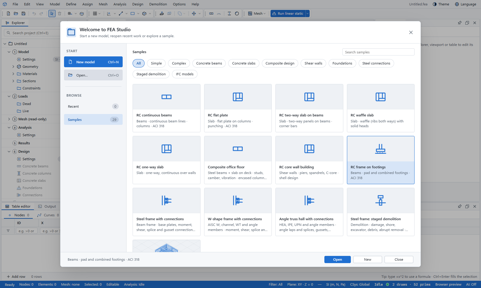
New to FEA Studio? Open File › Samples and run one first. Each sample explains itself in the Output panel.

The Samples page of the Start dialog: 29 worked samples, filtered by kind
02

Loads

Loads belong to load cases. FEA Studio writes your code’s combinations for each case type, so you only add what is special to the project.

  1. Define › Load cases: add dead, live, wind, seismic and other cases.
  2. Select members or faces and apply loads from the Assign menu: force, line load, area load, pressure.
  3. Let the code generators add gravity, live, snow, wind and earthquake loads (Assign menu).
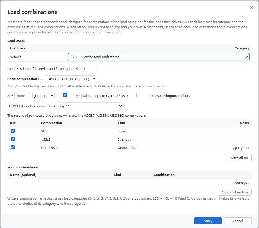
  4. Check Define › Load combinations; add your own beside the code ones.
The Load combinations dialog
03

Mesh

The mesh is built from the model and kept up to date for you. It is read-only: change the model, not the mesh.

  1. Open Mesh settings to set the element size.
  2. For solids and shells, choose the Netgen mesher if you need a finer, graded mesh.
  3. Check Mesh quality before a large run.
04

Analysis

A study is one analysis of the model: static, modal, response spectrum, pushover, time history and more.

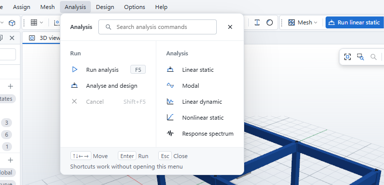
  1. Choose the analysis type from the Analysis menu; it adds a study to the Explorer. (You can also right-click Analysis in the Explorer and choose Add study.)
  2. Check the study’s settings and load cases in the Properties panel.
  3. Press F5 to run, or Analysis › Analyse and design to design straight after. Progress shows in a card; the log shows the result.

After an analysis the model is locked, so the results always match it. To edit, choose Results › Unlock model; that removes the results.

The Analysis menu: run commands and the five analysis types
05

Results

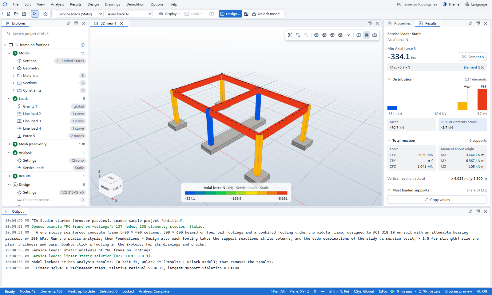
Choose what to show from the toolbar, then click anything in the model to see its values.

  1. Pick the study and the result (stress, displacement, member force) in the toolbar.
  2. Display: turn on the deformed shape and set its scale.
  3. Click a node or element; its values appear in the Results panel.
  4. Open charts and tables; they open as tabs beside the 3D view.
Member forces: axial force N in the beams and columns, drawn on the undeformed model
06

Design

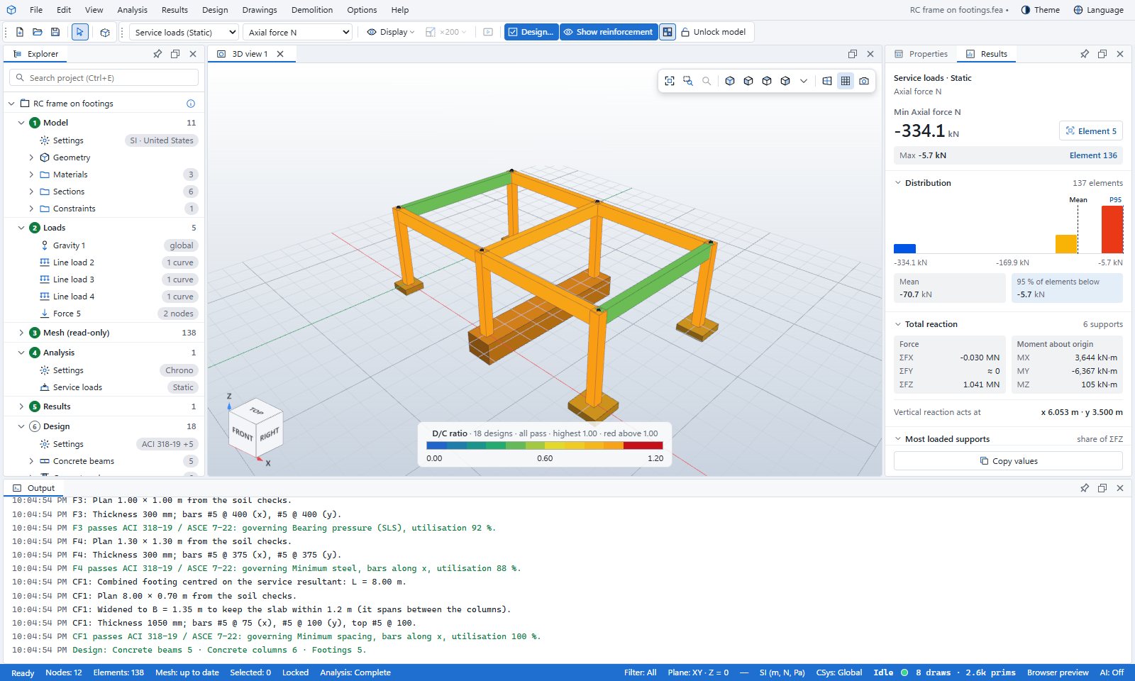
One button designs every member. The model is coloured by demand/capacity ratio: red is over 1.

  1. Click Design… in the toolbar and choose what to design.
  2. Read the Design summary when it finishes.
  3. Double-click a beam line, column, slab or footing to open its tab.
  4. Change bars or sizes there and re-run the check.

Set the smallest and largest bar sizes once for the project; every design keeps to them.

D/C ratios of a concrete frame on footings: every design passes
07

Drawings

Drawings are made from the designed members, so they change when the design does.

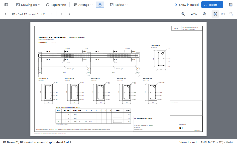
  1. Drawings › Create drawings… makes the whole set: drawing list, general notes, formwork plans, reinforcement sheets and schedules.
  2. Drawings › Drawing standards…: pick a preset, or adjust the options with a live preview.
  3. Open a sheet from the drawing list. Export saves the set as PDF or DXF, with NC1 files, bending data and lists.
A reinforcement sheet: beam elevations and sections with bar call-ups
08

Reports

Reports collect the model, the results and every design check into one paginated document.

  1. Explorer › Reports › Settings: language, paper size and sections.
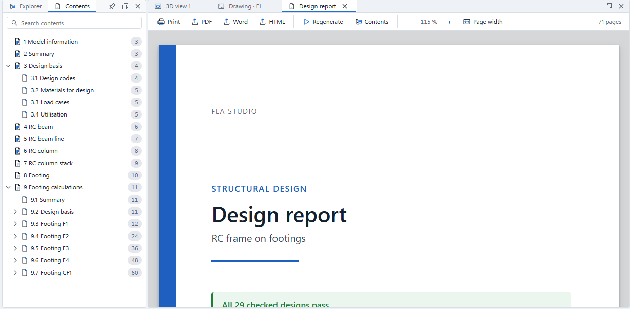
  2. Double-click Model report, Analysis report or Design report in the Explorer; it opens in a tab with its contents beside it.
  3. Print it, or save it as PDF, Word or HTML.
A Design report open in its tab: toolbar, cover page and page count

Keyboard shortcuts

F5Run the analysis
Ctrl+ESearch the project
Ctrl+SSave
Ctrl+Z / Ctrl+YUndo / redo
Ctrl+C / Ctrl+VCopy and paste objects
Ctrl+DDuplicate the selection
Ctrl+PReport
DeleteDelete the selection
Right-clickCommands for what is under the cursor

Go further

The user manual covers each stage in depth, with every dialog explained, in five parts: Modeling, Analysis, Design, Drawings and Reporting.